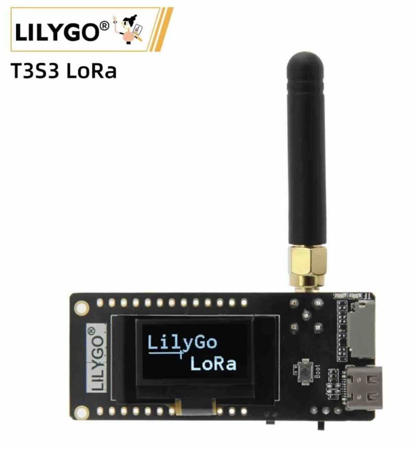
This new LILYGO T3S3 ESP32-S3 dev board is really cool because it combines many wireless things like LoRa, WiFi, and Bluetooth together in one small card. If you like making IoT projects or sending data to far places without using cellular data, this small board is very useful for you. It is the new version of the old LoRa32 series and it has the new ESP32-S3 chip inside which makes it fast and has more storage. Many people use it to make smart things for farms, smart cities, or just to talk to other devices far away. The board is small, about 79 by 22 millimeters, so you can put it inside a small plastic case or your pocket easily. It also has a tiny screen on top so you can see what is happening without connecting it to a computer.
The main brain of this board is the ESP32-S3 chip, which is a very popular microcontroller. This chip is good because it has 4 megabytes of flash memory and 2 megabytes of PSRAM, which is enough to run simple programs and store some files. It also has built-in 2.4 gigahertz WiFi and Bluetooth 5.0. This means you can connect the board to your home router or to your mobile phone to send data or change settings easily. You can write your code for this chip using Arduino IDE or MicroPython, which are very friendly for students or hobbyists who are just learning how to program. There are also boot and reset buttons on the board to help you when you want to upload your code or if the board gets stuck.
Now let us talk about the LoRa part, because this is the most important feature of this board. Lilygo offers different versions of this board with different LoRa chips like SX1280, SX1276, and SX1262. If you choose the SX1280 version, it uses the 2.4 gigahertz frequency band. This is very nice because the 2.4 gigahertz band can be used in every country in the world without worry about local radio laws. But if you need very long distance in specific countries, you can choose the SX1276 or SX1262 versions which work on 868 megahertz or 915 megahertz. The SX1262 is newer and uses less power when receiving signals, only about 4.6 milliamperes, while the older SX1276 uses 9.9 milliamperes. Each module has different power outputs, like SX1262 can go up to 22 decibel-milliwatts, which helps the signal travel through walls and trees.

There is a very important warning if you use the SX1280 model with the power amplifier. You must be very careful with the power settings in your code because if you make a mistake, you can break the board. The makers of this board say you must control the output power of the SX1280 chip to be between 2 and 5 decibel-milliwatts. If you do this, the power amplifier chip will raise the signal power to a safe 20 decibel-milliwatts. If you set the SX1280 chip power higher than 5 decibel-milliwatts, it will send too much power into the front-end module chip and it will burn and stop working forever. The best setting is 3 decibel-milliwatts because it gives you exactly 20 decibel-milliwatts output without any danger. If you set it lower than 2 decibel-milliwatts, the output will be less than 20 decibel-milliwatts, which is safe but you will not get the maximum distance.
The board also has a very nice little display screen on the front. It is a 0.96-inch OLED screen with a resolution of 128 by 64 pixels. The driver chip for this screen is SSD1306, which has many libraries available in Arduino so it is very easy to show text or simple drawings. The screen has a blue background and shows white text, which looks very clean and is easy to read even when it is dark outside. The screen connects to the main chip using I2C interface. The pins used for this are IO18 for SDA and IO17 for SCL, so you must define these pins in your code when you start the screen library. Having this screen on board means you do not need to buy extra wires or screens to see your sensor data or check if your LoRa message was sent successfully.
If you want to do voice communication, there is a special version of this board called the MVSRS version. This version comes with extra parts for sound. It has a MAX98357A speaker amplifier and an MSM261S4030H0R microphone. It also has a small vibration motor inside. With these parts, you can make a walkie-talkie project that sends your voice over the LoRa network to another board. This is very cool for places where there is no phone signal, like deep in the forest or in the mountains. You can talk into the microphone, the chip converts it to digital data, sends it over LoRa, and the other board plays it on the speaker. The vibration motor can shake to let you know when someone is calling you or when a message arrives.

Let us look at the pins configuration for connecting other sensors to this board. If you have the SX1262 version, the internal connection uses specific pins that you must know for your code. The Chip Select is connected to IO7, the Reset pin is connected to IO8, and the SPI pins are IO5 for SCLK, IO6 for MOSI, and IO3 for MISO. The DIO1 pin is connected to IO33 and the Busy pin is connected to IO34. If you have the SX1280 version, some pins are different. The TX pin is IO10, the RX pin is IO21, the Chip Select is IO7, the Reset pin is IO8, SCLK is IO5, MOSI is IO6, MISO is IO3, DIO1 is IO9, and the Busy pin is IO3. You must write these pin numbers correctly in your setup code, or the LoRa chip will not respond when you try to send or receive packets.
For power, this board is very flexible. You can plug a USB Type-C cable to power it from your computer or a phone charger. But if you want to make it portable, you can connect a 3.7-volt lithium polymer battery to the battery connector. There is a small battery switch on the board so you can turn the battery power on or off easily without unplugging the wire. The board also has a built-in battery charging circuit, so when you plug in the USB cable, it will charge the battery automatically. There is also a TF card slot on the board. This is very useful if you want to log data over a long time, like recording temperature from sensors every minute. You can just save all the data inside a microSD card and read it later on your computer.
To program this board, you can find many example codes on Github. The main repository is under the name Xinyuan-LilyGo. They have sample codes for both Arduino IDE and MicroPython. If you are a beginner, Arduino IDE is probably easier because you can just download the libraries for ESP32-S3 and LoRa and then upload the test code. If you have any problems or if your code does not work, you can go to their GitHub community and write a description of your problem, and their engineers will try to help you. It is a good idea to check the examples first because they already have the pin definitions and power settings configured, so you do not make mistakes that can damage the board.
When you buy this product, you get a small cardboard box. Inside the box, you will find one T3S3 development board, two rows of 2.54 millimeter male pins with 13 pins each, one battery cable with a connector, and one LoRa antenna. You must connect the antenna to the board before you power it on, especially when you are testing the LoRa transmitter. If you transmit without the antenna connected, the energy has nowhere to go and it can overheat and destroy the transmitter chip. So always remember to screw the antenna on first. This board is really a great choice for anyone who wants to learn wireless coding or build simple and cheap tracking or communication systems.